. Manual")
Content ..
..


Content ..
..


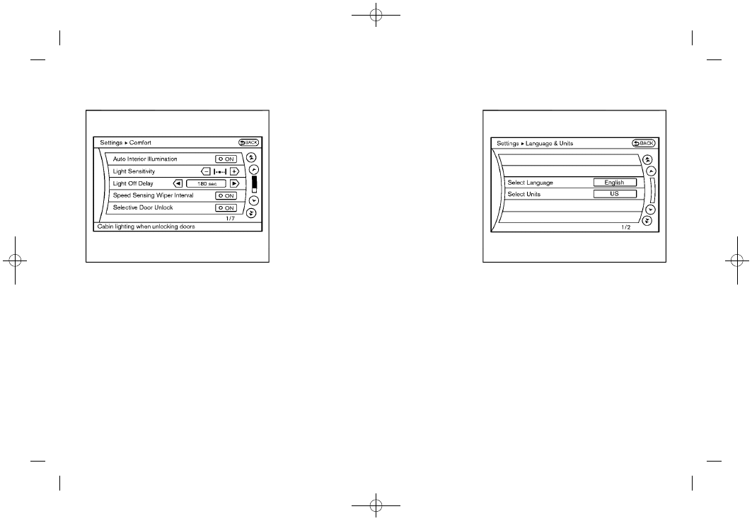
Comfort & Conv. settings
the button, selecting the “
Conv. ” key with the INFINITI controller and
pushing the button. This key does not
appear on the display until the ignition switch is
pushed to the ON position.
Auto Interior Illumination
When this item is turned to ON, the interior
lights will illuminate if any door is unlocked.
Auto Headlights Sensitivity (if so equipped)
Adjust the sensitivity of the automatic head-
lights higher (right) or lower (left).
Auto Headlights Off Delay (if so equipped)
Choose the duration of the automatic headlight
off timer from 0, 30, 45, 60, 90, 120, 150 and
180 second periods.
Speed Sensing Wiper Interval
When this item is turned to ON, the wiper
interval is adjusted automatically according to
the vehicle speed.
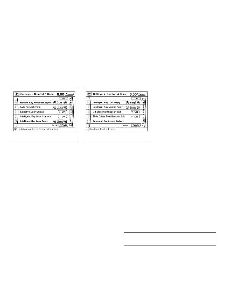
Selective Door Unlock
When this item is turned to ON, only the driver’s
door is unlocked first after the door unlock
operation. When the door handle request
switch on the driver’s or front passenger’s side
door is pushed to be unlocked, only the corre-
sponding door is unlocked first. All the doors
can be unlocked if the door unlock operation is
performed again within 5 seconds.
When this item is turned to OFF, all the doors
will be unlocked after the door unlock operation
is performed once.
Intelligent Key Lock/Unlock
When this item is turned to ON, door
lock/unlock function by pushing the door
handle request switch will be activated.
Lift Steering Wheel on Exit (if so equipped)
When this item is turned to ON, the steering
wheel moves upward for easy exit if the ignition
switch is in the OFF position and the driver’s
door is opened. After getting into the vehicle
and pushing the ignition switch to the ACC
position, the steering wheel moves to the pre-
Slide Driver Seat Back on Exit (if so equipped)
When this item is turned to ON, the driver’s seat
moves backward for easy exit if the ignition
4-16 Monitor, climate, audio, phone and voice recognition systems

Revision: 2004 November
Make sure mating surface of FPC (Flexible Print Circuit) andthe direction of connector terminal.
Remove screws (4) and clips (2). Then remove audio unit fromcluster lid C.
10. Remove audio unit screws (8), unified meter and A/C amp.
screws (2) and remove bracket.
When carrying audio unit body, do not touch internalmechanism access from cassette tape slot.
Be careful not to allow foreign material to enter from cas-sette tape slot.
Use appropriate screws for each, as screws for audio unitare different from that for unified meter and A/C amp.

Removal and Installation for A/C and AV Switch
Remove audio unit from cluster lid C. Refer to
Remove screws (8) and remove A/C and AV switch.
Installation is the reverse order of removal.

Remove steering wheel. Refer to
Remove screws (2) and remove audio steering wheel switch.
Removal and Installation of Front Door Speaker (Base system)
EI-30, “DOOR FINISHER”
Remove screws (4) and remove speaker.
Remove screws (4) and remove bracket.
Removal and Installation of Front Door Speaker (BOSE system)
Remove screws (3) and remove speaker.
Remove screws (3) and remove bracket.

Removal and Installation of Rear Door Speaker (Base system)
Remove door finisher. Refer to
Removal and Installation of Rear Door Speaker (BOSE system)

EI-38, “LUGGAGE FLOOR TRIM”
Connectors must be placed in the left side, when installed.
Removal and Installation of BOSE Speaker Amp.
Remove screws (4) and connectors (2) and remove BOSEspeaker amp. from luggage floor.
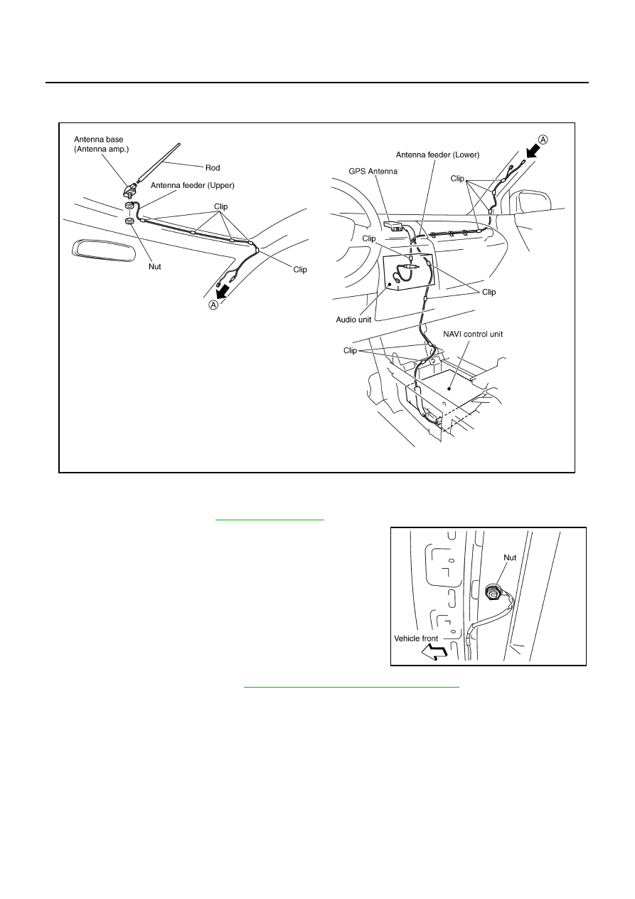
Remove nut and antenna base.
Remove instrument panel. Refer to
IP-10, “INSTRUMENT PANEL ASSEMBLY”
Remove antenna feeder (upper) and antenna feeder (lower).
Remove clips (5), and separate antenna feeder (upper) from vehicle.
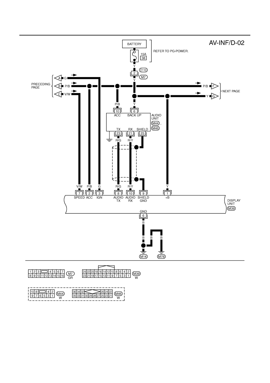
INTEGRATED DISPLAY SYSTEM
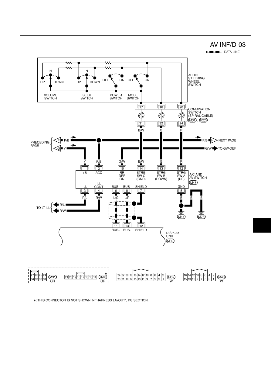
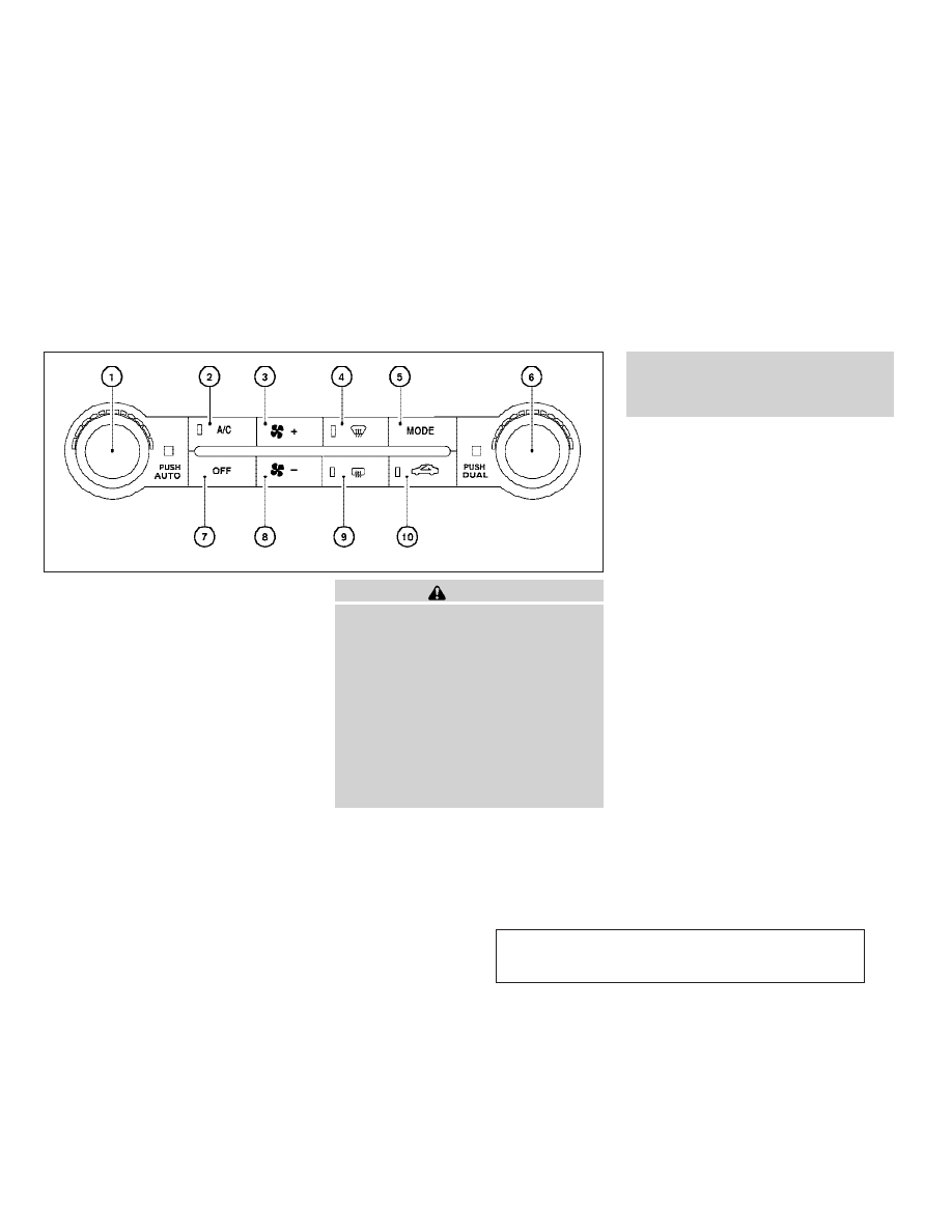
A/C AND AV SWITCH SYSTEM
Refer to Owner
Integrated display system (Drive computer, setting screen, clock, etc.)
PRECAUTION OF LCD MONITOR
In order to use LED for backlight of a display, by in car temperature, brightness may change. In low tem-perature, the refreshing rate of the picture also becomes low because of the low response of the LCDmonitor. When passenger room becomes warm, however, the LCD recovers the normal display.
Backlight sometimes flickers or darkens according to the total consumption hours and the number of timesswitched ON and OFF. In this case, display unit should be replaced.(Exchange only of backlight is impos-sible.)
POWER SUPPLY AND GROUNDPower Is Supplied At All Times
When Ignition Switch Is In ACC or ON Position, Power Is Supplied
to unified meter and A/C amp. terminals 29, 30
to BCM terminals 49, 52
through body grounds M14 and M78.
s Manual for drive computer operating instructions.
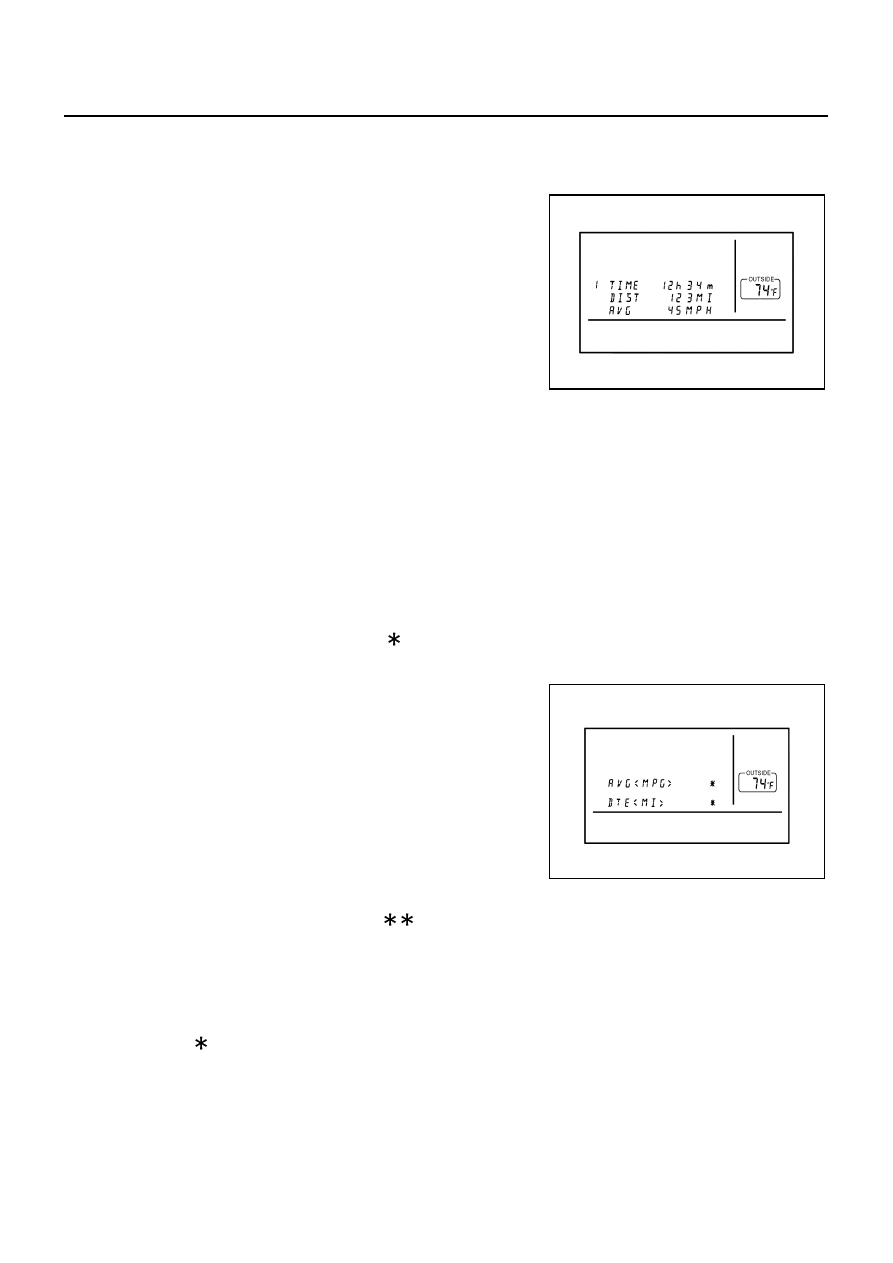
When “TRIP” switch is pushed, display TRIP screen. As TRIP infor-mation, it indicates journey time (TIME), trip odometer (DIST), andaverage vehicle speed (AVG).Pushing “TRIP” switch once cycles display from TRIP 1
Journey time indication is conducted by reset or battery connec-tion.
When pushing “TRIP RESET” or “TRIP” switch more thanapproximately 1.5 seconds, journey time will be reset.
If journey time is reset, journey distance and average speed willbe reset at the same time.
Trip odometer indication is conducted by vehicle speed signal.
When pushing “TRIP RESET” or “TRIP” switch more than approximately 1.5 seconds, driving distance willbe reset.
If trip odometer is reset, journey time average speed will be reset at the same time.
Average speed indication is conducted by running distance and running time.
When pushing “TRIP RESET” or “TRIP” switch more than approximately 1.5 seconds, average speed willbe reset.
After reset operation, the displays shows “ ” for 30 seconds.
When “FUEL ECON” switch is pushed, display FUEL ECON screen.As FUEL ECON information, it indicates average fuel consumption(AVG), and distance to empty (DTE).Pushing “FUEL ECON” switch once cycles display from FUELECON
Average fuel consumption indication is conducted by ECM pulsesignal and vehicle speed signal after system is reset.
When pushing “TRIP RESET” or “FUEL ECON” switch morethan approximately 1.5 seconds, average fuel economy will bereset.
After reset operation, the display shows “ . ” until the vehicle is driven 1,600 ft. (500 m) or 30 secondshas passed.
“DTE” (Distance to Empty)
Distance to empty receives via CAN communication and indicates values calculated by meter.
Display range is max 999 miles (max 999 km).
If low-fuel WARNING is received from combination meter via CAN communication, distance to empty indi-cation will be “ ”.
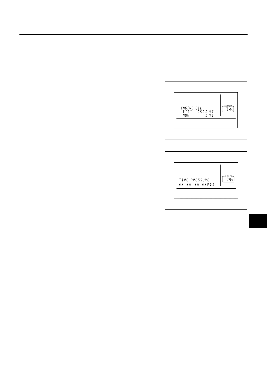
MAINT Switch (Maintenance Switch)
When “MAINT” switch is pushed, display vehicle information screen. As vehicle information, it indicatesengine oil, tire rotation, and tire pressure.
NOTE:There is not low tire pressure warning system becomes display OFF.
Operating the joystick left/right, replace distance can be set.
When journey distance is the same as replace distance, alert isdisplayed. (SERVICE ALERT setting is ON.)
Selected replace distance is 0 – 7,500 miles (0 – 12,000 km) inincrements of 500 mile (800 km).
Push and hold “TRIP RESET” or “MAINT” switch for 1.5 sec-onds or longer, reset present journey distance.
Tire pressure signal is received from low tire pressure warningcontrol unit via CAN communication.
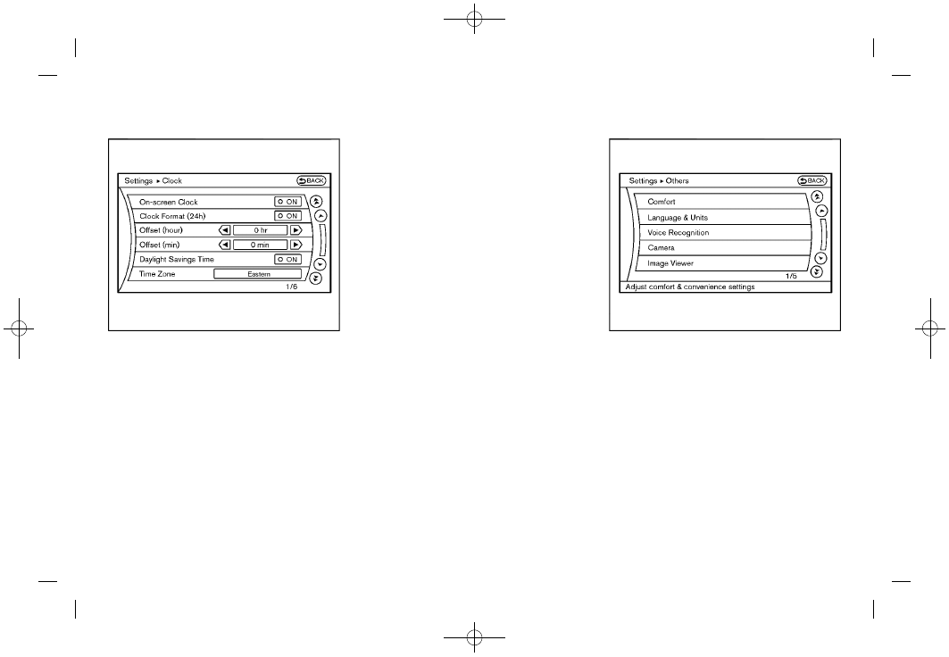
When “H” or “M” switch is pushed and held for 1.5 seconds or more, mode is changed to clock mode.
When “H” switch is pushed, “hour” is adjusted.

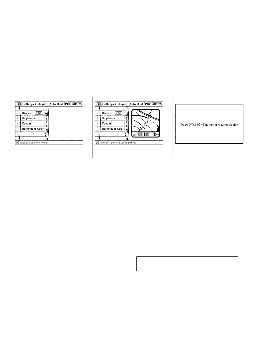
To turn off the display, choose “OFF” on the screen using the joystick.
To turn on the display, push display screen control, air conditioner or audio button.
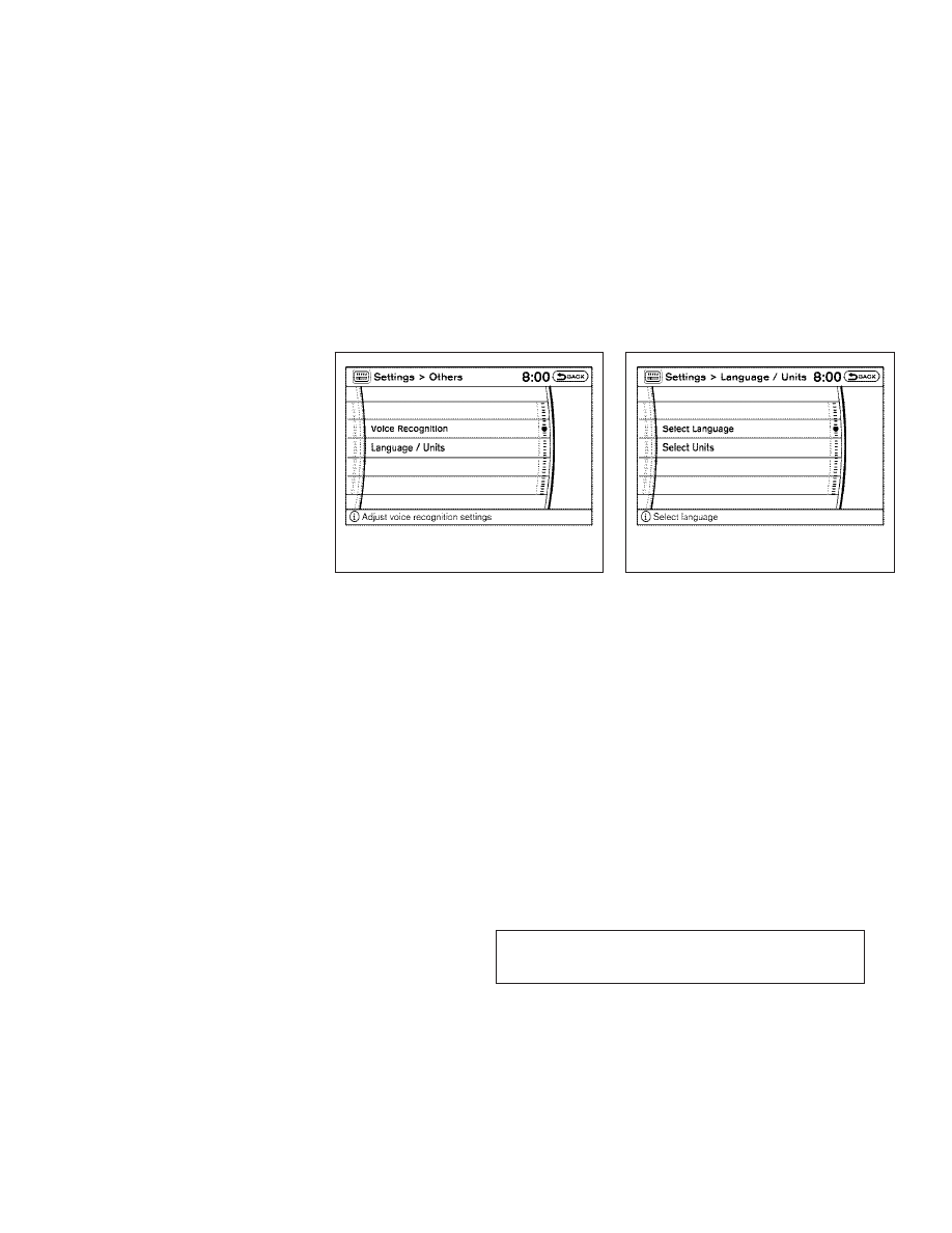
To change the language, choose English or French using the joystick.
To display the maintenance information on the screen when it has reached to the preset distance, choose “ON”.
SLIDE BACK DR SEAT ON EXIT*
To set the driver’s seat so that it automatically moves back and returns to the original position for ease of entry and exit, choose “ON”.
REMOTE UNLOCK DOOR LOGIC*
To set the unlock doors of the 1st unlocking operation, choose the desired function.Only the driver side door
HORN CHIRP WITH REMOTE*
To set the horn chirp mode that occurs when pushing the LOCK button on the remote controller, choose the desired function.
LIGHTS FLASH WITH REMOTE*
To set the hazard indicator flash mode when the “LOCK” or “UNLOCK” button on the remote controller is pushed, choose the desired function.
To set the auto door re-lock time, choose the desired time.
To set the sensitivity level of the automatic headlights, choose the level.
To set the time for how long it takes the automatic turn off timer to extin-guish the headlights in the AUTO position, select the “Automatic Head-lights Off Delay” key, then move the joystick to the left or right to adjust the timer.
SPEED SENSING WIPER INTERVAL*
To turn on the speed sensing wiper, choose “ON”.
To reset all settings of the personalized settings to the initial conditions, choose “YES”.
To reset all settings of the personalized settings to the initial conditions, push “ENTER”.

Push “PREV” or not operate for 10sec. when displayed screenof adjustment luminance, back to default screen (same mode).
Can adjust luminance by joystick (R/L) in adjustment screen.
Adjustment range is a 12 stage (MIN to MAX) and default set value is 10 (DAY) and 4 (NIGHT).
The door open warning will disappear when the vehicle speed slows down under 5 km/h (3 MPH) even ifthe door is not securely closed yet.
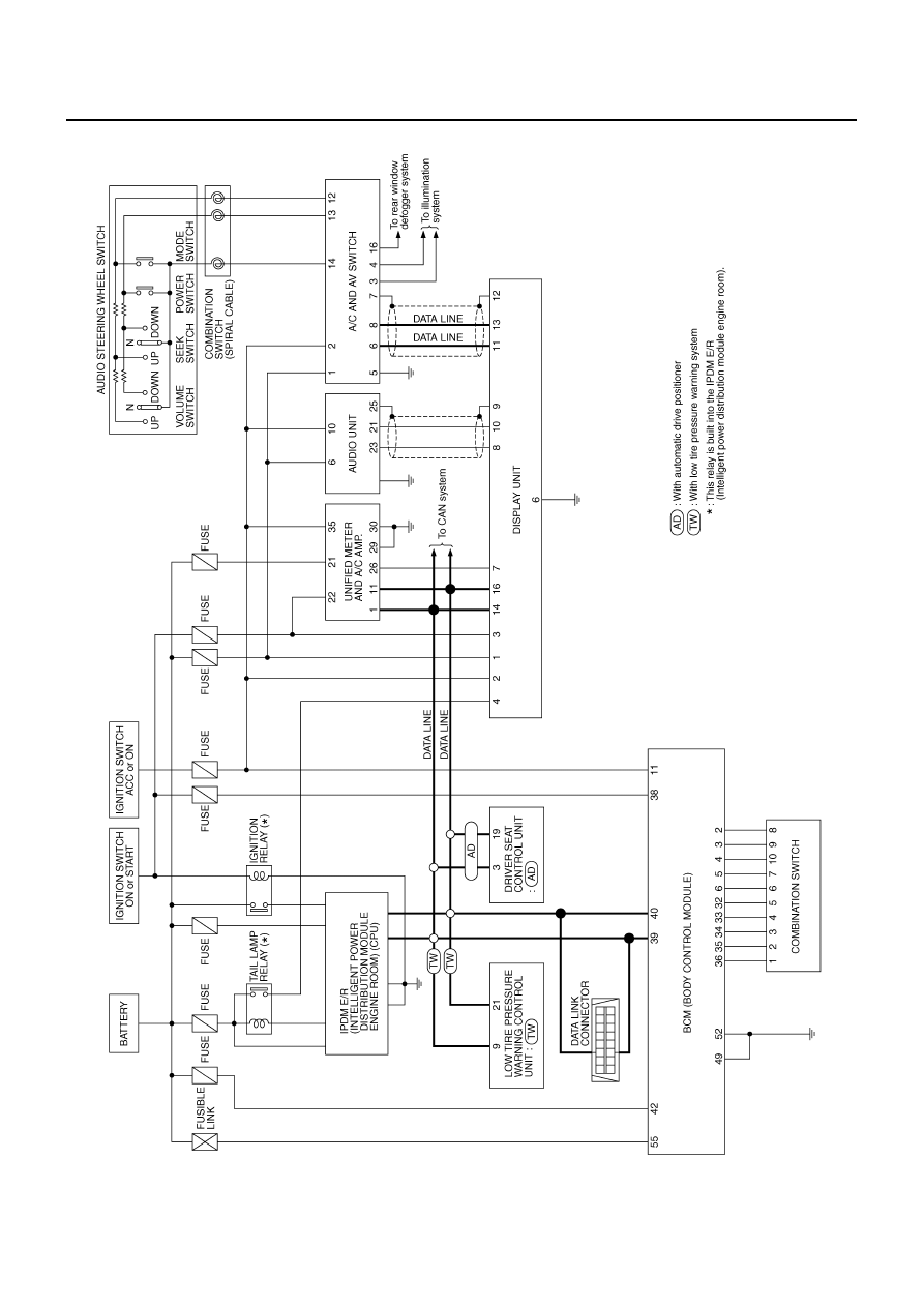

Wiring Diagram — INF/D —